Unlike previous calibration algorithms, the geometry of the Immersadesk is no longer of utmost importance. Gone are the days in which the Immersadesk had to be at a certain frequency, resolution, alignment, and position. Because the point (0,0,0) is now defined as the point in the center of the screen projection, the calibration meets this specification. Thus, only two things are necessary for a proper calibration.
First of all, the Immersadesk must be projecting in a linear fashion. Try pressing the # key on this remote:
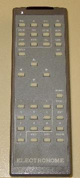 On the display that appears, the grid should have straight, evenly spaced lines. If this is the case, then the display is linear.
Furthermore, the display must be rectangular.
Back to topAlso unlike previous calibration algorithms, there is no longer a need for giant contraptions on which to rest the stylus in neutral position. Instead, there is a sleek fabricated plastic piece in which to cradle the stylus. Make sure the stylus is aligned within this cradle whenever commencing calibration or CHaMUE 2. You'll know when the arm is initializing because the phantom will make a loud thumping noise. Keeping the stylus aligned during initialization ensures maximal accuracy and repeatability.
While it's easy to just let the stylus rest in its cradle, make sure that during initialization that you are in contact with the stylus. This is a safety feature to ensure that the stylus is under control of a user at all times -- CHaMUE 2 disables this feature at all times except initialization.
Back to topUpon running the calibration program, the application will prompt you to place initialize the phantom and click ok. Once the phantom is initialized, you will be presented with a series of targets.
Each target is representative of a point specified in the configuration file. While the target is displayed on the screen, arm calibration points may be off the screen, such as at the reset arm, so the target serves as more of a reminder than as a placefinder. However, for points on the screen, the target is useful as a graphic on which to match the stylus. For each indication, you need to align the hinge of the stylus with the point requested.
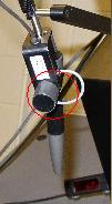
The joint circled is the hinge. The reason the hinge was chosen as the calibration point was because it is from where the phantom arm directly gets its positional values. Each point will appear several times in the calibration process -- for every time, take care to match up the stylus as accurately as possible to the point specified.
Back to topAs of the writing of this document, headtracking calibration is not a fully automatic process. It requires a bit of matlab work and thus, is not recommended for a casual calibrator. Fortunately, however, the headtracker does not need to be recalibrated unless the transmitter is moved, and so it is highly likely that the headtracker calibration file present in CVS is accurate.
Back to topThe configuration file is the file which specifies many variables about the calibration. Here is a sample configuration file, and an explaination of each feature.
calibration.cfg:
*CALIBRATION
SCREEN_HEIGHT_RES: 1024
SCREEN_WIDTH_RES: 1280
SCREEN_WIDTH_MM: 820.7375
SCREEN_HEIGHT_MM: 701.675
NUM_ITERATIONS: 2
NUM_POINTS: 5
POINT: 7.9375 284.1625 580.23125
POINT: -304.8 217.4875 0.0
POINT: 304.8 217.4875 0.0
POINT: -304.8 0.0 0.0
POINT: 304.8 0.0 0.0
*CALIBRATION
This must be on the first line of the file. It lets the calibration file know that this is indeed a calibration configuration file.
SCREEN_HEIGHT_RES:
This specifies the height of the screen, in pixels.
SCREEN_WIDTH_RES:
This specifies the width of the screen, in pixels.
SCREEN_HEIGHT_MM:
This specifies the height of the screen, in millimeters.
SCREEN_WIDTH_MM:
This specifies the width of the screen, in millimeters.
NUM_ITERATIONS:
This is the only non-required field in the configuration file. Specifies how many times to take a single point (for purposes of averaging). For debugging, set this to a low number, but for actual configuration a higher number is preferable. If not set, it defaults to 5.
NUM_POINTS:
This specifies the number of points in the file to the calibration program, so it knows how many to expect. This must be set before any points are specified, or the program will complain. Furthermore, this must be the exact number of points in the file, or again, the program will complain.
POINT:
This signifies a point that the calibration file should sample. The numbers are given in world coordinates (in millimeters) and the calibration procedure will find the matching phantom arm coordinates for each point.
Note: Make sure there is no additional carriage return after the last line. The file parser is not too fond of extra carriage returns.
Back to top